


| Place of Origin: | China |
|---|---|
| Brand Name: | Launch |
| Certification: | CE |
| Model Number: | S2-2 |
| Minimum Order Quantity: | 1 piece |
| Price: | Best price |
| Packaging Details: | Standard Package |
| Delivery Time: | Within 48 hours |
| Payment Terms: | TT/PayPal /Western Union/ Money Gram |
| Supply Ability: | In Stock |
| Function: | Diagnosing/testing/simulating Most Vehicle Sensor Faults | ||
|---|---|---|---|
| High Light: | launch x431 super scanner,scanner launch x431 |
||
Launch X431 S-2 Sensorbox USB Oscilloscope 2 Channels Handheld Sensor Simulator and Tester
Launch X-431 Sensorbox S2-2 Description
LAUNCH S2-2 Sensor box module is specially developed for diagnosing/testing/simulating most vehicle sensor faults. With its help, users can easily and quickly diagnose and simulate the sensor to rapidly troubleshoot the ECU.
At the same time, the LAUNCH S2-2 Sensor box module also supports the vehicle multimeter function. Through this function, users can test voltage, resistance, and capacitance. The function uses the same hardware device as the sensor module. The module cannot be used separately, and must be used together with Launch-specific diagnostic tools that are compatible with this module. It can be compatible with LAUNCH scanner X-431 PAD V and X-431 PAD III V2.0.
The sensor is the signal input device of the vehicle ECU. It converts vehicle operating parameters such as vehicle speed, coolant temperature, engine speed, air flow, and throttle opening into electrical signals and sends them to the vehicle ECU. Then, the vehicle ECU adjusts the engine running status to maintain the engine in optimal condition.
Launch X-431 Sensorbox S2-2 Features:
![]()
Functions:
S2-2 Sensorbox is specially developed for diagnosing/simulating sensor faults. LAUNCH S2-2 sensor box mainly includes "Sensor", "Actuator", "Defined/Drawn", and "Timing Waveform".
Sensor: Is used to simulate the input signals of the automobile electronic control system, and the automobile computer adjusts the running state of the engine according to these parameters.
Actuator: Is used to simulate the output control signal of automobile electronic control system, so as to judge the working conditions of automobile actuators such as idle motor, EGR solenoid valve, etc.
Multimeter: Through this function, users can test voltage, resistance, and capacitance.
The module cannot be used separately, it only works as accessory for LAUNCH X-431 PAD III, PAD V and PAD VII diagnostic tools.
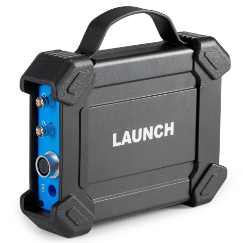
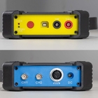
S2-2 Sensorbox Connection:
1) Insert one end (B-type terminal) of the USB cable into the B-type USB port of the sensor module host, and then insert the other end into the USB port of the diagnostic tool.
![]()
2) Press and hold the power button for over 3s to start the sensor module. If the electric quantity is normal, the green lamp is steady on Indicator lamp status description:
Green lamp:
Steady on: normal electric quantity
Flashing at an intermediate speed: low electric quantity (regardless of whether red lamp flashes)
Flashing at a low speed: charging in progress
Red lamp:
Steady on: diagnostic tool connected
Flashing: diagnostic tool disconnected. It will enter the charging status only when the red lamp is flashing. The green lamp is flashing at a low speed during charging.
3) Start the diagnostic tool and access the toolbox. Tap Sensor Simulator to access the job menu of sensor.
Job Menu:
The sensor module is mainly divided into five functional modules
![]()
1) Sensor: Use output voltage or waveform to simulate the working status of the on-board sensor, so as to accurately judge the quality of the sensor and reduce blind replacement of accessories.
2) Actuator: Used to output PWM signal to drive the on-board coil actuator.
3) Defined/Drawn: Users can customize sensor waveforms to facilitate future sensor signal simulation.
4) Timing waveform: Customize timing waveform to match the engine (crankshaft + camshaft), and output in the same phase.
5) Multimeter: universal multimeter functions.
Defined:
Waveform: There are 9 waveforms to choose; Forward sine wave, reverse sine wave, forward square wave, reverse square wave, medium voltage, straight line, high / low voltage straight line, triangle wave, and trapezoidal wave.
Frequency: Set the frequency of the selected waveform.
Amplitude: Set the amplitude of the selected waveform.
Offset: Set the offset of the selected waveform.
Phase: Set the phase of the selected waveform.
Duty cycle: Set the duty cycle of the selected waveform.
Signal sync: Can cause CH1 and CH2 to output signals at the same time.
Hand-drawn:
Total frame: 1-3 (optional). Indicate the total number of output points
Generally, one waveform is composed of 100 points. The values 1-3 indicate that you can select 100, 200, or 300 points to form a waveform.
Edit frame: You can edit a single frame or edit all
Waveform: You can select a preset waveform and place it in the hand-drawing area
Frequency: Frequency of a single frame (for 3-frame output, the total frequency is the set frequency/3)
Amplitude: Amplitude of the output waveform
Offset: Offset of the output waveform
Timing Waveform:
The function is used to match the timing waveform (crankshaft + camshaft) of the engine.
Technical Parameters:
Sensor Module:
Number of channels: 2
Precision: 1 %
Amplitude range: 0 – 20 V
Max output current: 20 mA
Predefined frequency range: 0 – 20 kHz
Square wave signal pulse frequency: 0 – 15 kHz
Square wave signal duty cycle: 0 – 100 %
Power supply: Simulator sensor output/max current 20mA (output is powered by battery) – Drive solenoid, ignition coil/output current 2A (external power supply)
USB: USB2.0 Type B (with charging and power supply function/5V)
DC voltage simulation: Support
Fixed frequency simulation: Support
Predefined waveform simulation: Support
Hand-drawn waveform simulation: Support
Signal generator interface: 2
External power supply port: 1
Solenoid interface: 1
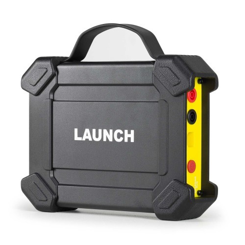
Multimeter interface: 2
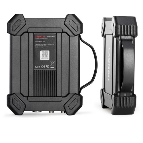
Working temperature: 0 °C – 50 °C
Storage temperature: -30 °C – 70 °C
Multimeter:
DC voltage: 0 V – 700 V
AC voltage: 0 V – 700 V
Resistance: 0 Ω – 40 MΩ
Capacitance: 0 F – 100 µF (maximum 30 s measurement time)
Diode: 0 V – 1,5 V
Continuity detection: Sounds below 30 Ω
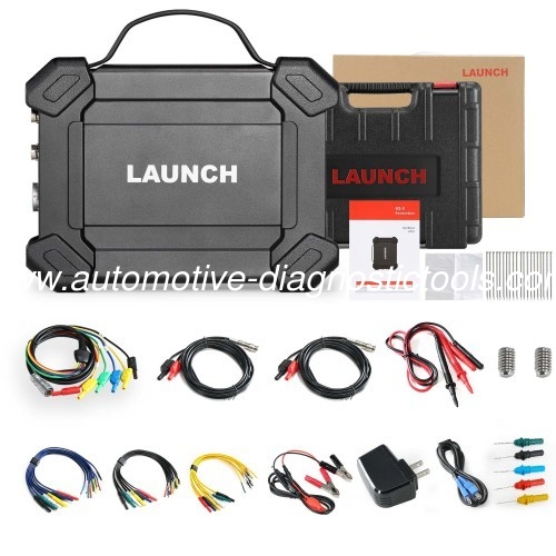
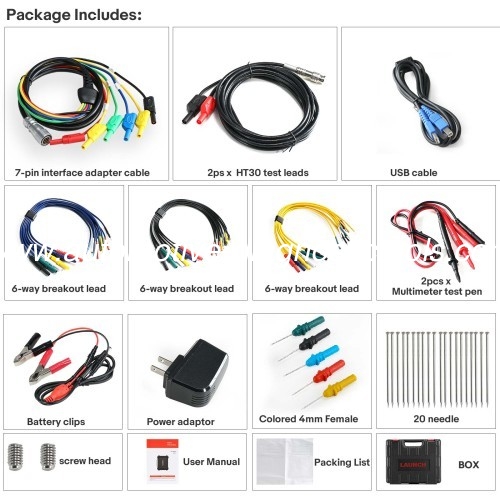
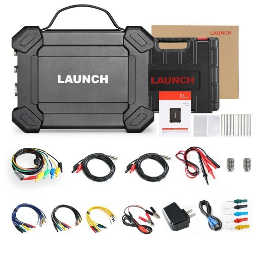
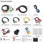
Package List:
1pc x Sensor module
2ps x HT30 test leads
1pc x 7-pin interface adapter cable
1pc x Battery clamps cable
1pc x USB cable
3pcs x 6-way breakout lead
2pcs x Multimeter test pen (black + red - )
5pcs x Colored 4mm female probes
20pcs x Needles
1pc x Power adaptor
2pcs x Screw heads
1pc x User manual
1pc x Packing list
1pc x Box
![]()